
What is a plate heat exchanger?
A plate heat exchanger transfers energy between fluids at different temperatures. Thin metal plates provide the transfer surfaces, with the hot and cold fluids on opposite sides. The intended operating principle keeps the circuits separate rather than mixing the fluids. The exchanger does not generate heat like a boiler or provide the temperature lift of a heat pump by itself: it passes energy from one stream to the other under the conditions established by the complete system.
The plate pack, gaskets and frame
In a gasketed unit, formed plates are held between fixed and movable frame plates. Heat crosses the thin plate surfaces. Gaskets seal the channel edges and direct fluid from the ports into the intended channels. The frame, supports and tightening components maintain the mechanical arrangement. Brazed and welded units use different joining methods; the maintenance approach of an openable gasketed unit cannot simply be transferred to them.
From four connections to parallel channels
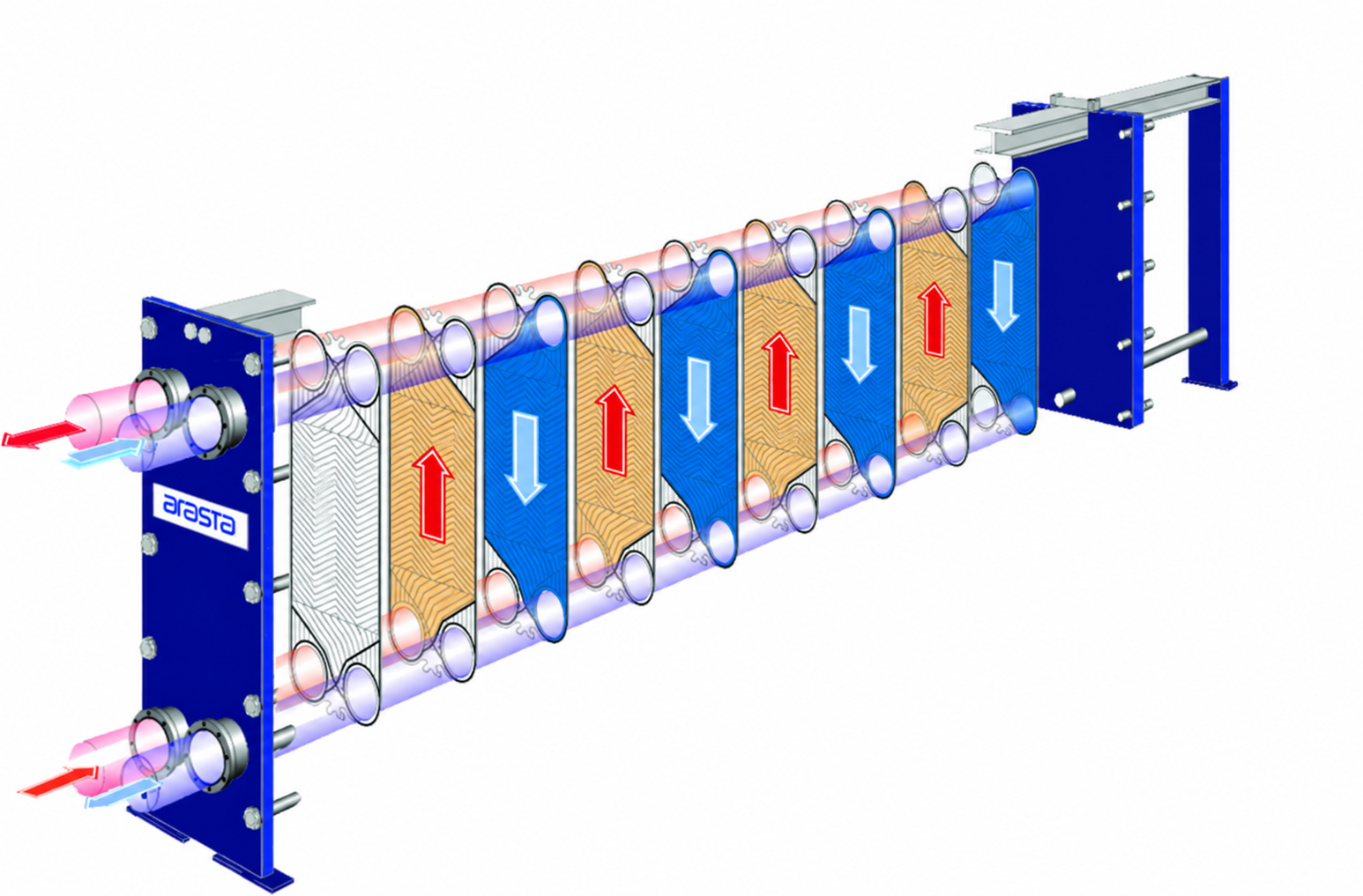
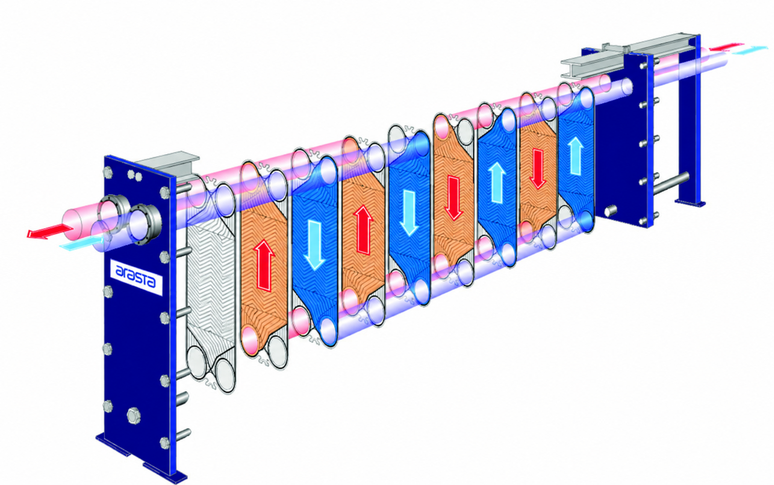
A common two-circuit liquid/liquid arrangement has an inlet and outlet for each circuit. Corner ports form distribution and collection passages through the pack. Port and gasket arrangements direct each fluid into its own channels, beside channels carrying the other fluid. A stream is distributed across groups of parallel channels rather than necessarily passing through a single channel. Connection positions are model-specific: the actual equipment drawing takes precedence over the colours in an illustration.
How heat crosses the plate
The hot fluid transfers heat to its plate surface, energy travels through the metal by conduction, and the opposite surface transfers heat to the cold fluid. In a suitable liquid/liquid duty the hot stream cools while the cold stream warms. Performance depends on fluid properties, surface area, flow arrangement and temperatures, not plate thickness alone. Deposits can add thermal resistance. The moving traces show fluid direction; they do not measure heat propagation through the metal or the actual temperature field.
Why use countercurrent flow?
In countercurrent flow, fluids in adjacent channels travel in opposite directions. The temperature-difference profile differs from that of parallel flow and may permit close terminal approaches under suitable conditions. The cold outlet can be warmer than the hot outlet because these outlets are at different ends of a countercurrent exchanger. Feasible targets must nevertheless be checked against inlet temperatures, flow rates and duty. No universal approach temperature or efficiency percentage can be inferred from this illustration.
Single-pass and multipass arrangements
Single-pass flow travels across a group of parallel channels before being collected; it does not mean there is only one plate or channel. A multipass arrangement directs the fluid through successive channel groups, with a change in direction between passes. The two exploded-view animations illustrate this distinction. More passes are not automatically better: thermal duty, channel velocity and allowable pressure drop must be assessed together.
What does the plate pattern change?
Formed surfaces create the channels and support contacts within the pack and influence distribution across the surface. Plate pattern and channel geometry affect both heat transfer and hydraulic resistance. A geometry intended to improve heat transfer can also change the pressure drop the pump must accommodate. Particles, fibres and viscosity bring additional passage and cleanability requirements. Channel spacing is not an allowable particle diameter.
A simple energy balance
For a single-phase liquid, heat duty can be approximated by mass flow × specific heat × temperature change: Q̇ = ṁ × cp × ΔT. For example, water at 1 kg/s with a specific heat taken as approximately 4.18 kJ/(kg·K) requires about 41.8 kW for a 10°C rise. This is an energy-balance illustration, not a device rating or plate-count calculation. Convert volumetric flow using density. Phase-changing duties require an enthalpy-based assessment rather than this simple expression alone.
Operating principle is not a product rating
Knowing the direction of heat transfer does not establish permitted pressure, temperature or fluid compatibility. Confirm plates, joining materials, gaskets where fitted, both circuit design conditions and the pressure–temperature envelope for the exact model. Do not combine a family pressure maximum with a temperature from another document. Existing equipment needs its nameplate and technical records; new selection needs current manufacturer documentation and thermal/hydraulic calculations.
Apply the principle to your requirement
Record both fluids, inlet and target outlet temperatures, flow rates and allowable pressure losses. Include composition, concentration and cleaning conditions that affect compatibility. Opening access, service space and future duty changes also influence the equipment family. This article explains principles rather than installation, tightening or chemical-cleaning procedures. Continue with the equipment-family comparison and quotation checklist to prepare a coherent engineering enquiry.
Prepare for the discussion
- Fluids, composition and relevant material requirements
- Flow rates and inlet/outlet temperatures on both circuits
- Design conditions and allowable pressure drop on each side
- Exact model, nameplate and current technical documents